2007 Chevy Silverado Brake Controller Wiring Diagram Yarn Aid
Presented by Hayman Reese technical towing expert Gary Gardiner, watch the typical installation process of Hayman Reese Brake Controllers, including end-to-e.

Ford Trailer Brake Controller Wiring Diagram A Guide For Beginners Moo Wiring
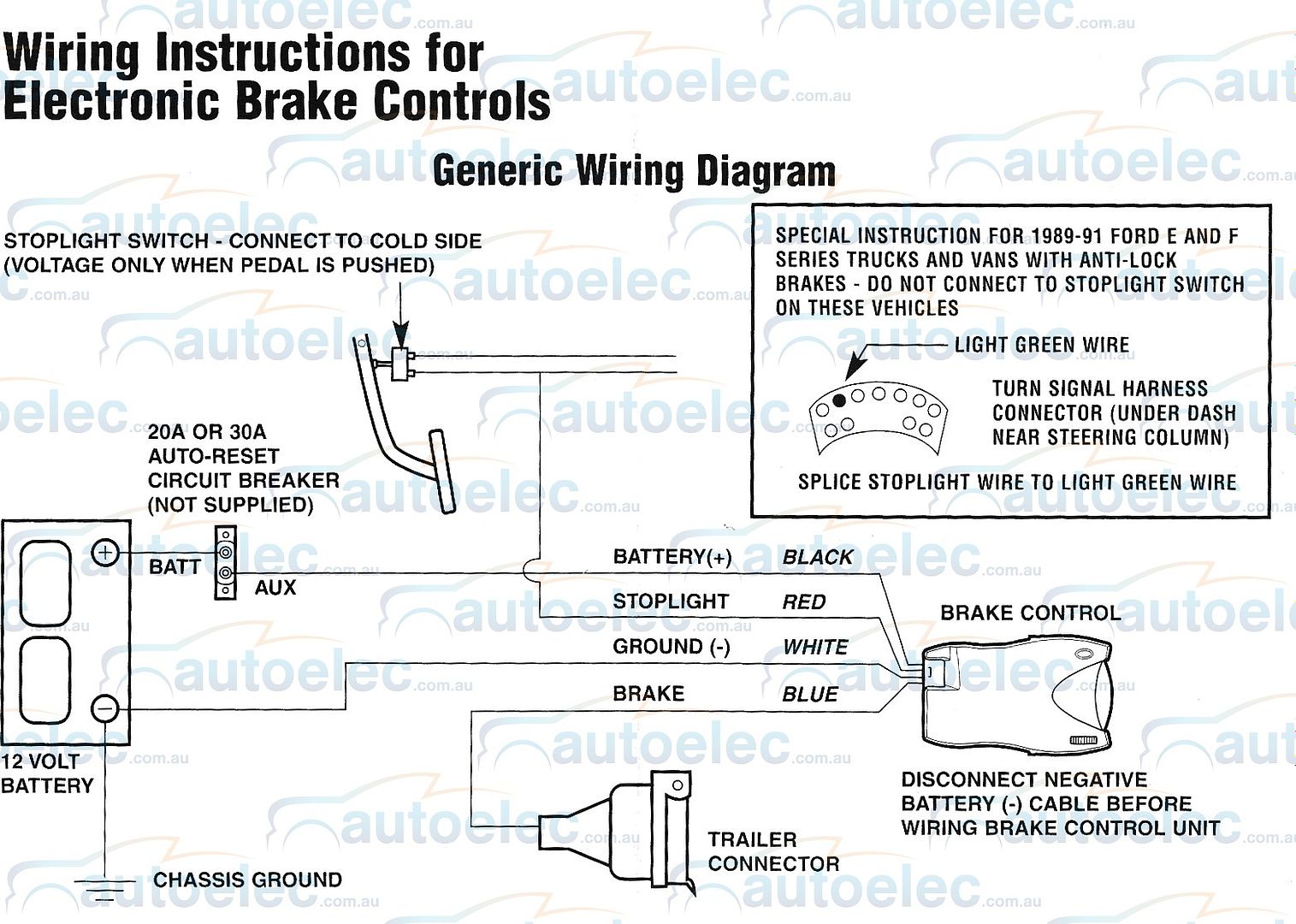
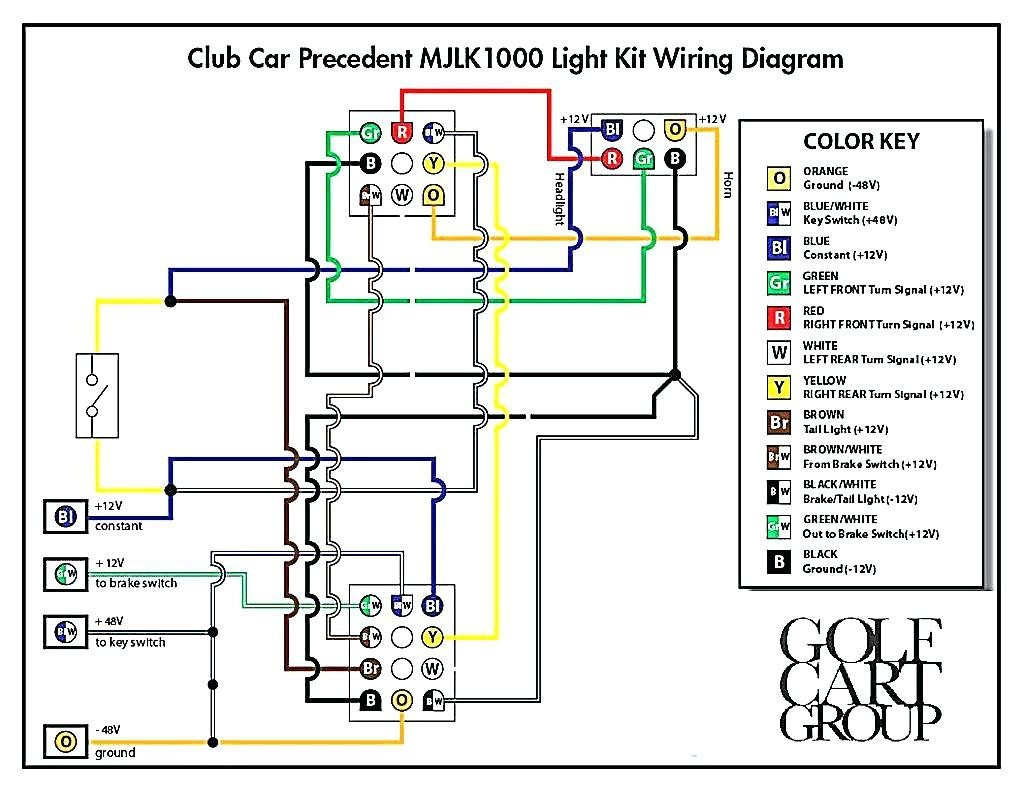
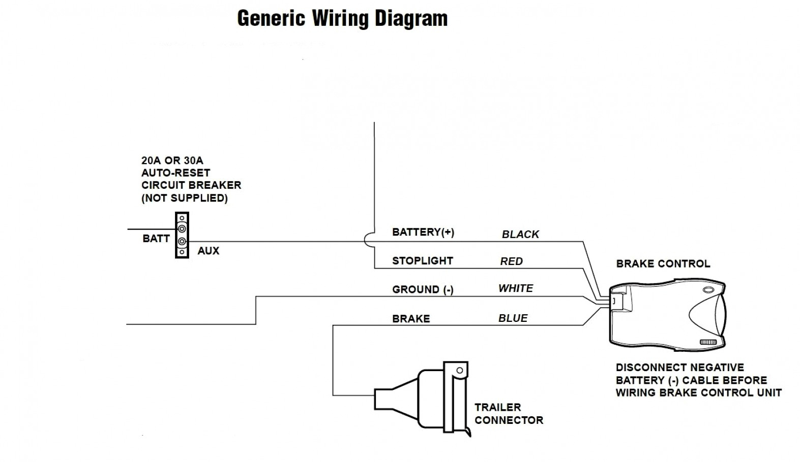
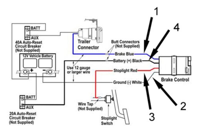
White wire - ground/negative terminal (-) on battery Blue wire - trailer electric brakes Black wire - positive terminal (+) on battery Red wire - cold side of stop lamp switch or brake light CAUTION:Wire colors vary by manufacturer. Be sure to wire by function only. VEHICLE MANUFACTURER WIRING CODES:
Electric Brake Controller Complete with Leader Cable to Wire to Trailer Elecbrakes
Connect the Brake Controller as Follows: GM Wire to Brake Control Wire Function Red/Black Black Battery Power White White Ground Light Blue/White Red Brake Light Signal Dark Blue Blue Brake Output to Trailer Orange N/A Center High Mount Stop Lamp (CHMSL)

Reese Pod Brake Controller Wiring Diagram paceinspire
Want a brake controller with no installation? Check out Echo™ How to install a trailer brake controller video Brake Control Install: CURT 51120 Discovery Brake Control Watch on Step 1: Disconnect the negative battery cable Any time you work on your vehicle's electrical systems, it is a good idea to disconnect the battery.
Brake Controller Installation Kit for a 1999 Toyota 4Runner with Tow Package
The standard brake controller wire colors are white for ground, red for the stoplight switch connection, blue for the electric brake lead to the 6- or 7-Way plug, and black for the 12V brake controller power connection. Connect the factory or aftermarket adapter to the brake controller according to function.
Primus Electric Brake Controller Wiring Diagram
Page 1 GENESIS Electronic Brake Controller Hayes Brake Controller Company - P/N 81790 INSTALLATION MANUAL For trailers with 2-8 electric brakes and vehicles with 12 volt negative ground systems only. READ AND SAVE THESE INSTRUCTIONS • Before beginning installation, read and become familiar with these instructions.
Ford Trailer Brake Controller Wiring Diagram Cadician's Blog
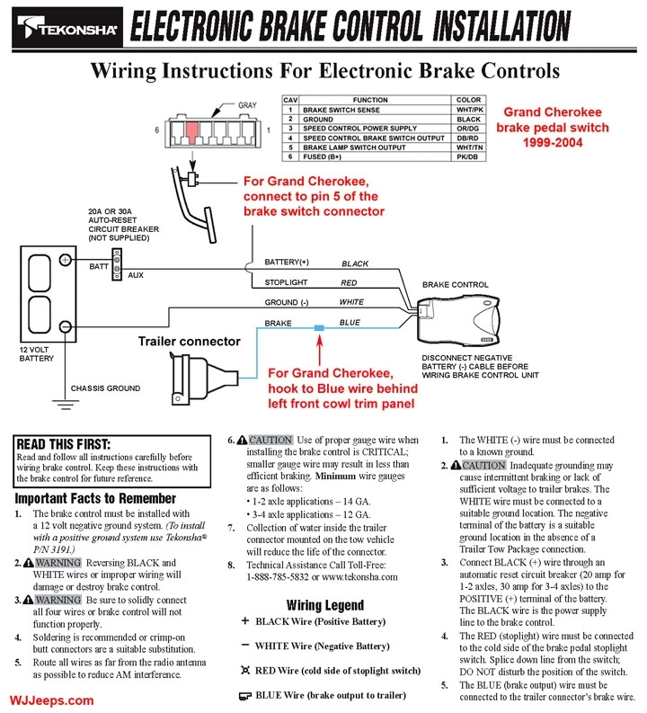
The wire needed is the light green wire, second from the end in the outside row of seven wires (see the box shown in wiring the diagram). Splice the brake control brake control's red wire to light green wire using a wire tap. Using 10 gauge stranded wire and ring terminals, connect the "BATT" side of the circuit breaker to the positive battery.
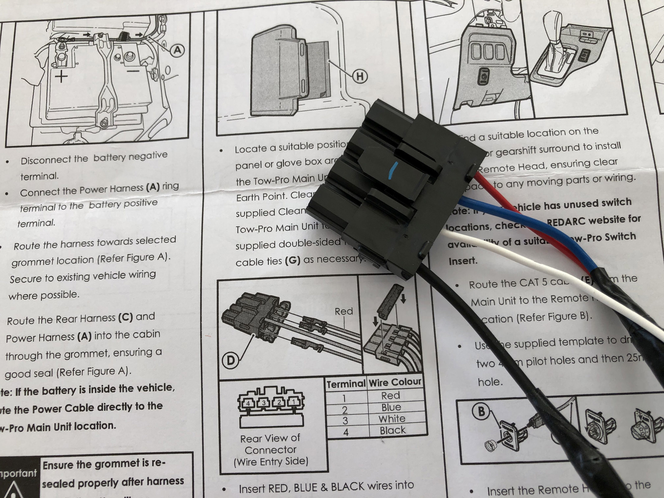
How to Install a REDARC Tow Pro Brake Controller
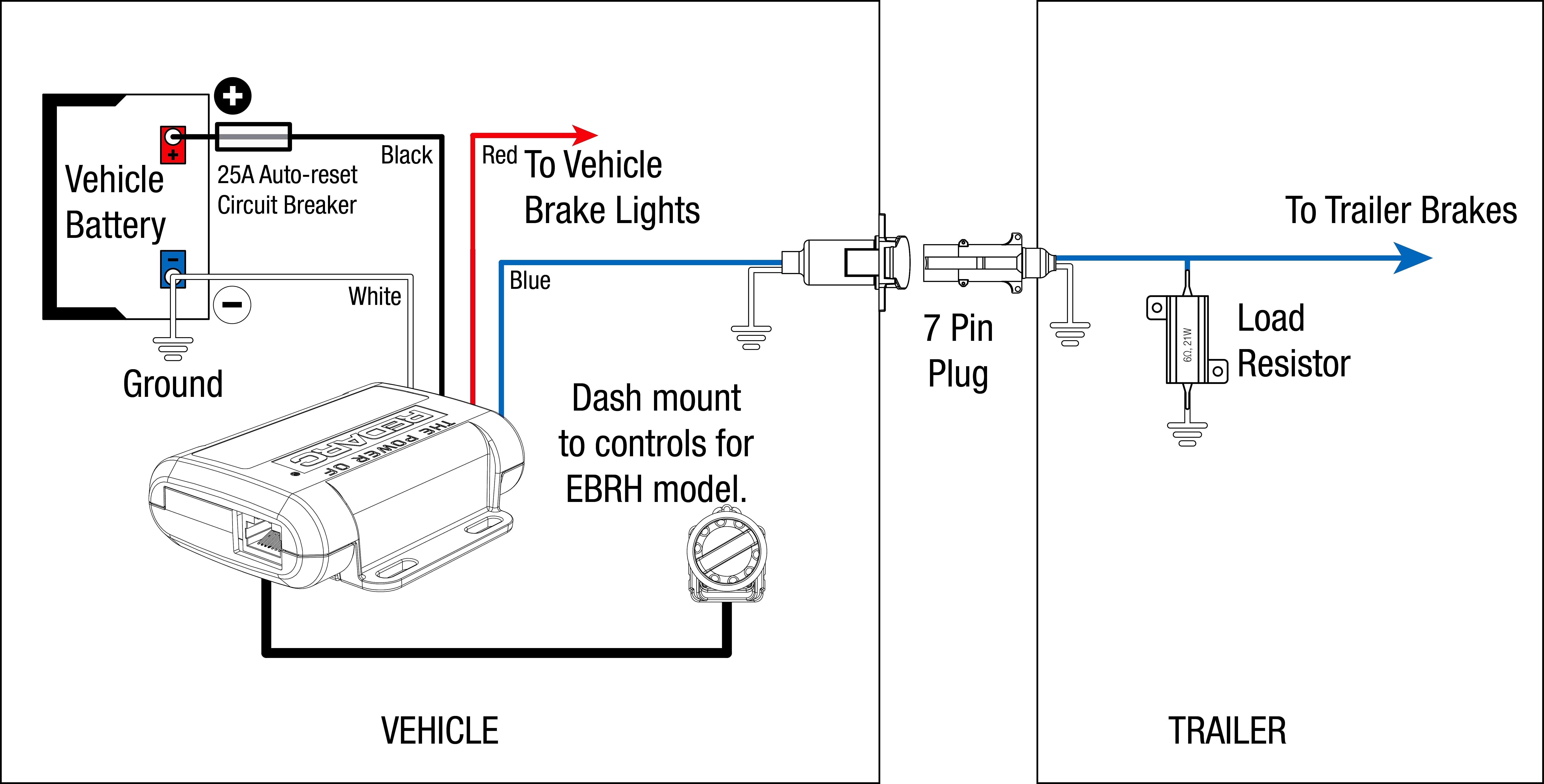
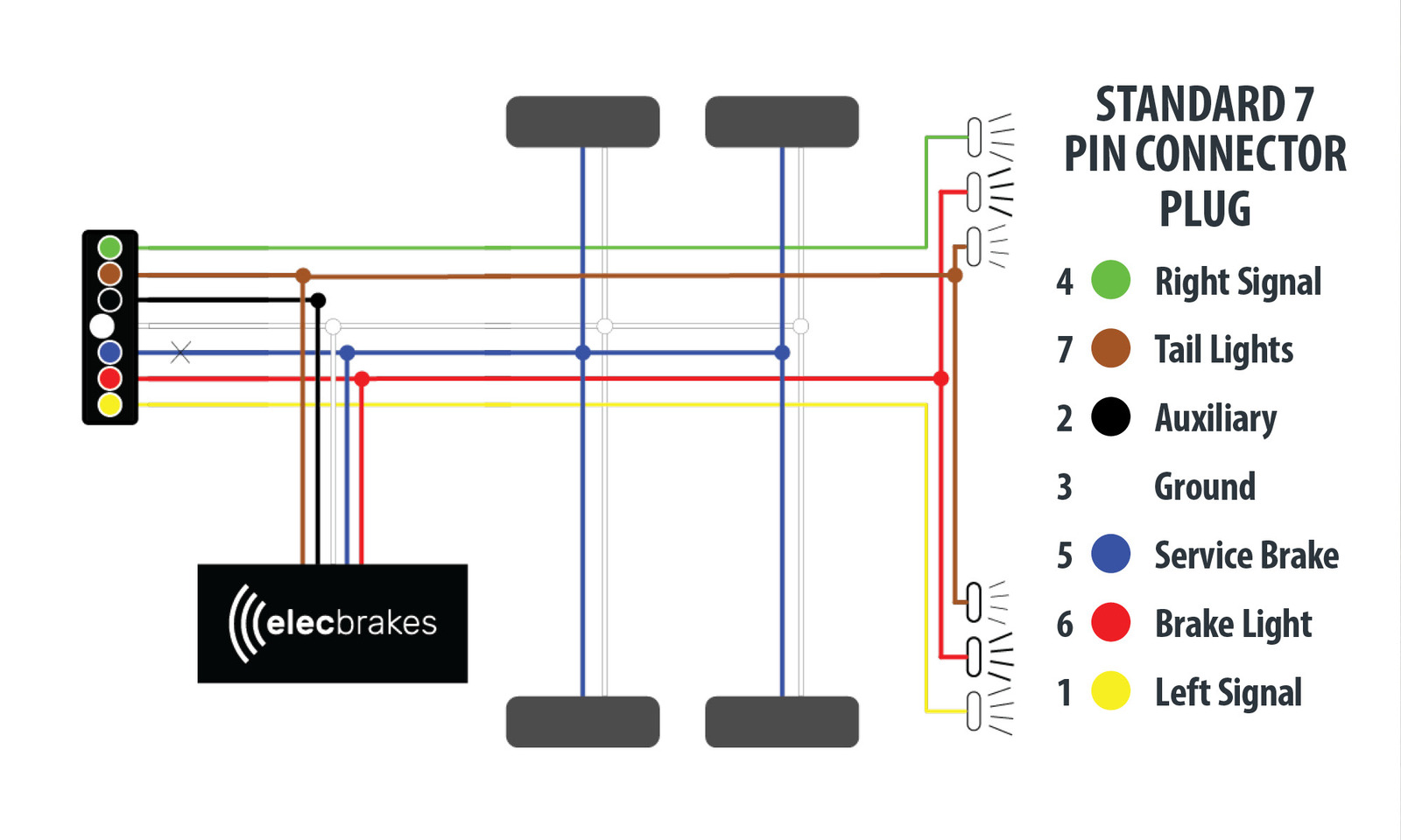
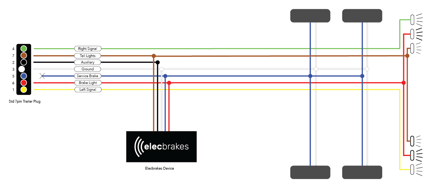
Electric Brake Controller Wiring Diagram. Wiring Diagram. Auxiliary connection is optional, it may be connected to any 12v to 24v constant power source or left unconnected. Break away systems may be added to the service brake circuit. Elecbrakes is designed to operate 1 to 2 braked axles. Get

Aron Wiring Wiring Diagram For Trailer Plug With Electric Brakes Kit Diagram Free
Rugged, adventure proof gear. Exploration without limits. Power that won't let you down. Phone. Tech Support Line: 1300 733 272. Head office number: +61 8 8322 4848. About Us. Contact Us.
Redline Brake Controller Wiring Diagram Images Of Brake Controller Wiring Diagram Cadician's
Figure 1. Trailer brake controller harness. The wiring color code for the factory harness is: Red with Black Stipe - 12 Volt Power Solid Blue - Trailer Brake Voltage Solid White - Ground Blue with White Stripe - Brake Signal

Wiring Diagram For Redarc Electric Brake Controller
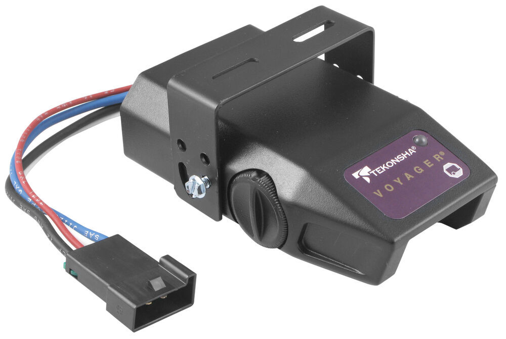
2. Insert Prodigy Brake control. 3. Plug in connector. For 2, 4, 6 and 8 brake applications Components of the Brake Control A. Power Knob B. Boost Button C. Manual Knob D. Connector (For Wiring Harness) E. Mounting Hole (1 per side) Important Facts to Remember 1. Do not mount or activate RF generating items (cell phones, two way radios) near
Wiring Diagram For A Tekonsha Trailer Brake Controller Collection Wiring Collection
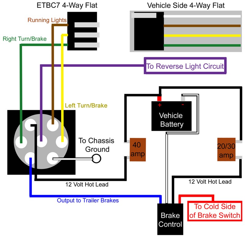
attach the white wire from the battery area to the brake control's white wire. Run a 12 gauge, or larger, blue wire from the tow vehicle's trailer plug 'brake' terminal to the brake control. Using a 10/12 butt connector, connect this wire to the brake control's blue wire. Connect the brake control's red wire to the cold side
Impulse Brake Controller Wiring Diagram Easy Wiring
The three basic wiring functions are for tail lights, stop lights and turn signals. NOTE: This 4-pole installation is vehicle specific. If your vehicle does not already have its own 4-pole trailer connector, use the Wiring Fitguide to find the harness recommended for your vehicle. The Colors of the Remaining Four Wires:

2013 Toyota Tundra Brake Controller Wiring Diagram The Human Tower
Wiring diagram for brake controllers A brake controller wiring installation kit makes light work! The following diagram is a general guide for wiring common brake controllers into cars. Please ensure you have the correct gauge wire and we do recommend you use an auto-electrician to wire the brake controller into your car.
Electric Brake Wiring Grounding Out
Brake Controller Wiring + Diagram Overview metaspencer 57.8K subscribers Subscribe Subscribed 325 Share 33K views 3 years ago #brakecontroller #dumptrailers Bumper-to-bumper overview of the.
prodigy p2 brake controller wiring diagram Wiring Diagram
In that case the device would be configured as per the following electric brake controller wiring diagram. For more information on how electric brake controller option using our hard-wired option, see our handy installation guide. 3. Connect Device using smartphone app.